Have you considered the Cube flight controller? Its a pixhawk 2 but in a much more convenient form factor for mounting on motherboards like this one.
If (big if) you were willing to sponsor your own version of the blheli esc, you could do it card edge style, like a ram stick. This would let you put many more esc on the board because they are vertical not flat. These esc are cheap to make, <15 usd per unit.
Arduino design is open source. You could put an arduino chip and clock, rather than a whole arduino board and save a lot of space.
We need a way to get more signals out from the 4 inch electronics pod, and an easier way to add and remove thise signals. If there was a way to interface this motherboard to the rear bulkhead with a single connector that would make it a lot easier to work on the electronics pod.
What do you think of adding a real mission comouter that could run a neural net, like a TX2? Thats a big differentiator in unmanned stuff rthese days
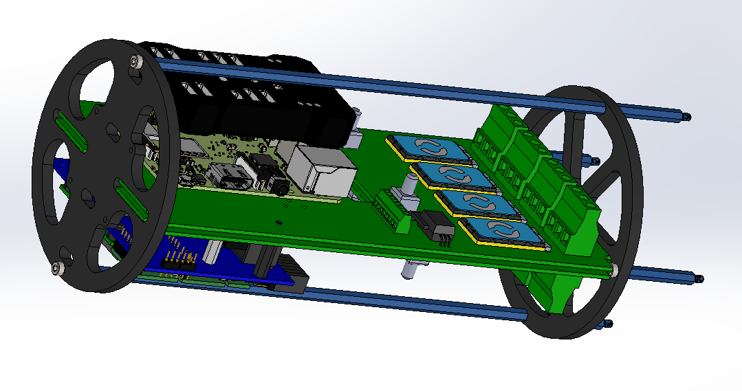
The first objective of this board is to be compatible with all BR2 so that I can reach as many potential customers as possible.
I have designed a piggy back relay board and a piggy back arduino board to go with it. Each board has a fan to cool off the ESCs. Once I finalized the position of the holes, I will be finishing my step files and post new topics on them.
I will also add a piggy back board on top of the RaspPi for the pixhawk with 90 degree female header connector and some opto isolators in the near future.
I haven’t considered it as of yet. That said I am not very happy with the pixhawk 2.4.6 because it is very expensive. I purchased a 2.4.8 to see if I can make it work with BR2 but I haven’t had the time to try yet.
I would be open to change flight controller in the future in the future as long at it remains compatible with the BR2 software because I do not want to get into that. Not for now anyway.
I would say in the future I would definitely want to. I do not like to have to surface mount the ESC and would like to have a connector on the side so we could easily replace them.
I considered that but an arduino nano is dirt cheap and I can add logic gates to increase the amount of I/Os. Its also nice to be able to replace it.
For now my relay board will do 2 x 10A relay 2 30A relay there are limited space and its all I could fit.
Arduino board will provide additional 2 pwm
I do not know if you have ever worked with ROVs before. I am an ROV Superintendent with 19 years offshore by the way. From my experience, the more connectors you put the more unreliable a system gets.
The Br2 is reliable because there are very few connectors. Fork connectors will rarely get loose.
What I’ve seen a lot is a stab plate with DB-type connectors and pogo pins for power transmission.
In the meantime, I would like to get plugable terminals to be able to unplug and plug back without to have to unscrew the wires but I cannot find any that will fit the form factor and rated to 30A.
This way we could use extensions and work on the pod easily because I agree its a big pain.
Any suggestions? Pitch is 6.35mm
Initially I am working on BR2 compatible products.
I am also building a commercial version and I want that one to be on a gigE network so I will be looking at better SBCs.
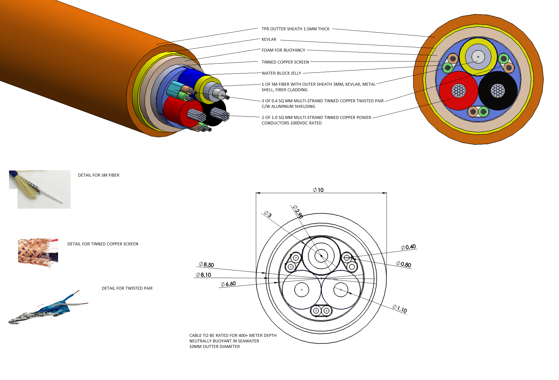
It might be hard to get gige down the tether unless we switch to fiber. But thats going to require someone to step up and order ten million feet of cable to get the price down. Id like a fiber copper combo so i can do high voltage tether power and high speed data.
Do you know what the market could be for an untethered, autonomous BR2 with the underwater gps and onboard collision avoidance for site surveys (like coral reefs) and photo pointclouds like people do with drones on land?
My friend does Robotic Ocean, which makes aluminum subsea housings. Is there any value in making a 3rd party BR2 electronics pod that can go down to ~1km with an aluminum housing? It would need the fiber tether.
Auterion, Lorenz Meyers company that makes the Pixhawk sw needs a sort of all in 1 UxV motherboard with a gpu or SBC, some mpcie slots, and easy esc interfaces and power monitoring. A similar thing, or the same thing might be perfect for small rovs. Ardusub is fully compatible with pix 4 hardware. Auterion is doing all of the software, and is presently adding in collision avoidance. The only thing they dont have is a sort of demo platform. They partnered with this one company to make a demo drone and they fell on their face.
I’m just flinging out ideas as they come. Some of them are going to be stinkers. Ill keep thinking out loud here and on the BR forum.
I agree that being BR compatible is the best course of action early on. But that still leaves a wide range of possibilities. The ESC and interfaces seem like the most annoying thing about the existing BR2. Soldering, card edge connection, an 8-pack ecu are all potential simplifications. Making the back more servicable is also a goal, though youre are right that more connectors is not necessarily good. Getting more signals out the back for more payloads would be good too.
Do you use solidworks 2018? Do you use Altium? Im a pretty good ee and layout artist. I can do bga and high density, high speed, and high power stuff. Figuring what specifically I should make and what are the requirements is the hardest part. I want to work on something others will find useful!
You must already have some sort of tether power system. Can you tell me about it? What fiber-ethernet converters are you using? What kind of connector? Do you have a way to add an inline connector to the Fathom tether so you don’t need to take the endcap off to separate the tether and ROV?
I made a tether power system prototype. I think it needs the addition of a current comparator for safety to detect fault current. That’ll be part of the next rev. And I might boost the voltage higher. This one was sized to deliver 300W (1A 300V) for 300m over 2 twisted pair to power the BR2.
But I have no practical experience with tether power systems. Never used one. Never had an ROV before. What’s wrong and whats right?
I am redressing 220VAC to make 310VDC. Using a 750W 12VDC DC-DC subsea.
Plan is to make a DC 3x step-up for my Delta 1 ROV and a 3x step down subsea but still use the same existing 750w design. As you know, managing heat dissipation is critical for power system.
I do not have a tether fiber connector as those are crazy expensive. What I do is use a BR 2inch enclosure as a termination box and remove the cap…
I saw your tether prototype. Looks very neat. How you have it well protected.
When I used the Fathom-X tether I used to use a mini-wetcon 8x. That would work perfect for your system.
Heat turned out to be pretty critical. After I turned it off and pulled it, the dc/dc had made so much heat the endcaps popped off on the table once the air inside absorbed enough heat.
Would be nice to have endcaps that could not pop off.
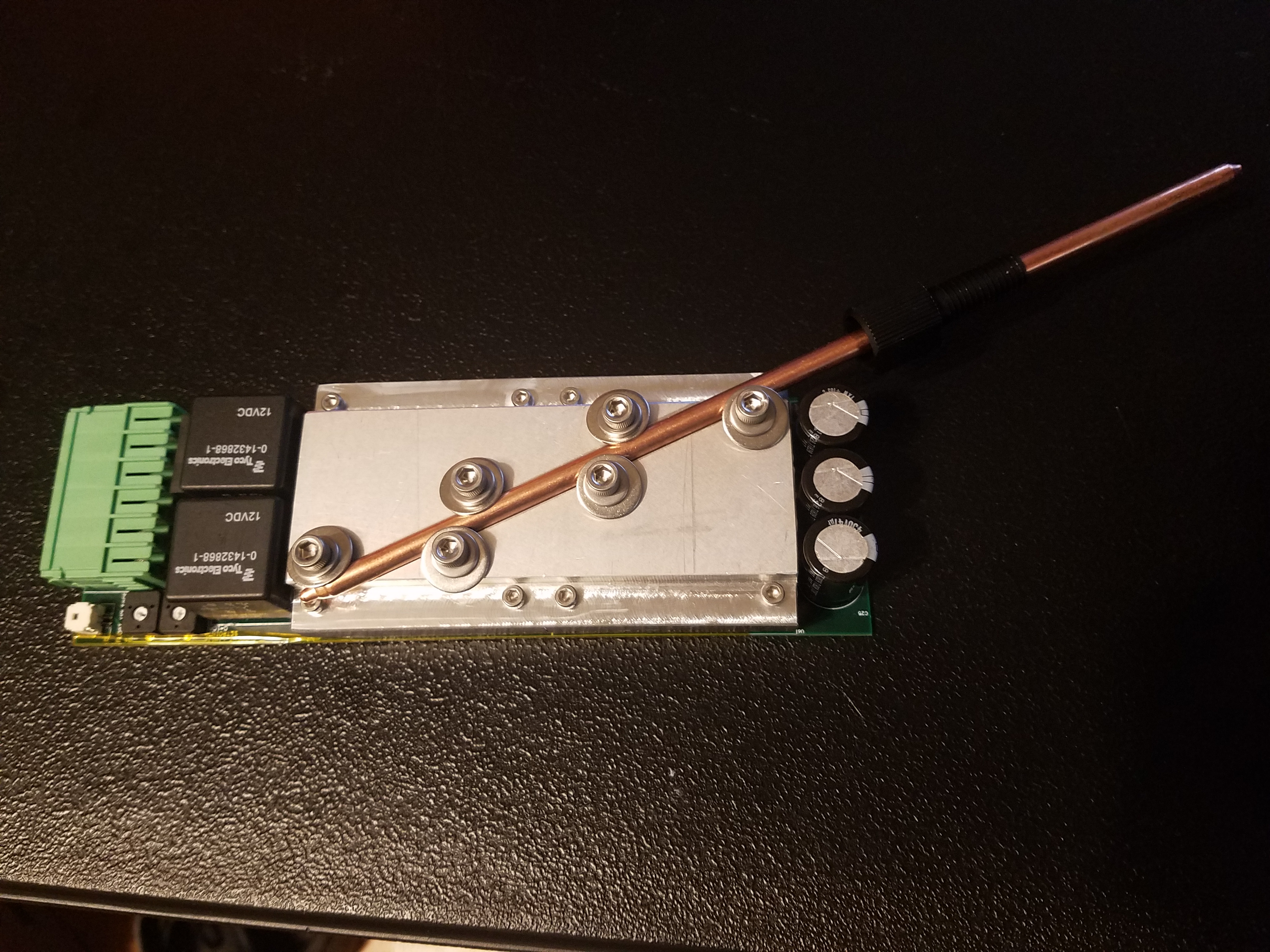
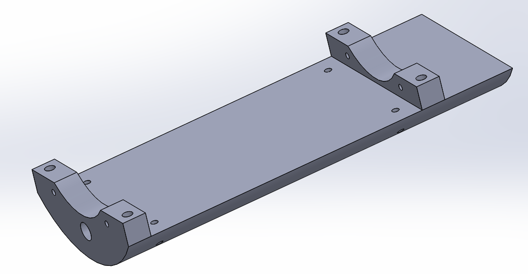
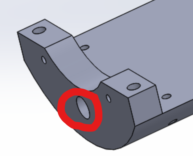
So, putting aside the fact that the endcaps come off, I made this heat block and I am going to use a heat-pipe through the bulkhead. Hopefully the thixtropic epoxy stuff BR sells will stick to the copper, and hopefully it does not un-stick when the pipe gets hot. Time for some artistic bending.
My thermal solution was not properly thought out ahead of time. I want to put the thing in the water ASAP without having to make new endcaps and get them anodized (and a new cnc heat sink and new board). I usually don’t “wing it” but today I am impatient. $7 for the heatpipe and it’ll be watertight by tomorrow.
You know what would be nice: an off-the-shelf endcap with a thermal solution of some kind. Maybe a heatpipe passthrough with a 12V fan, or a couple tapped holes to put a heat sink like yours.
Next revision of this board I will do better by adding current feedback for safety as well as a proper thermal solution.
I will be selling all this as a kit so it will be available by itself.
The idea is the DC-DC plate is mounted on this heatsink which is mounted against the aluminum housing. A clamp on both end with screws and nuts wedges everything against the aluminum enclosure.
Put in some heat paste and let the ambiant water cool it off…
Your heat pipe idea to me is a good way to flood your pod.
Yeah im definitely a dumdum for not thinking about heat when I did the pcb design. Que sera sera.
Next rev will be compatible with a heat sink bolted to the enclosure. I like that you are working on a range of accessories for the br2.
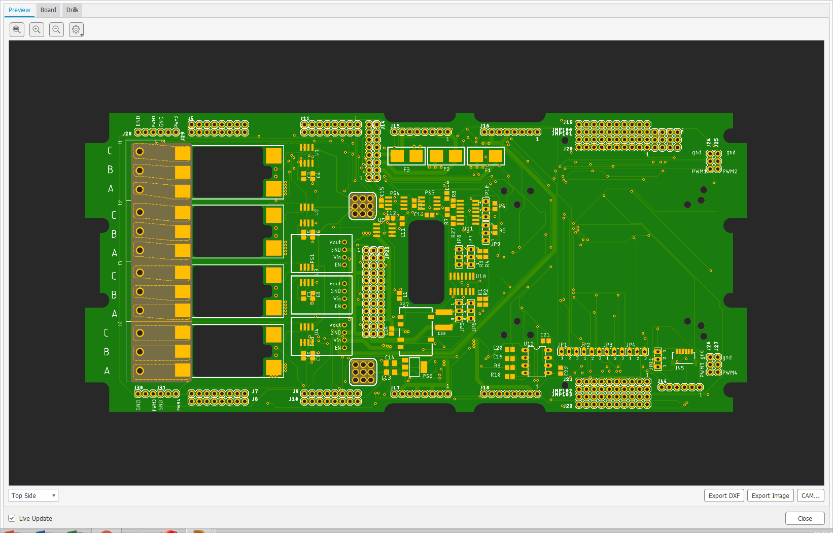
Ill throw together an esc concept to look at, and post it here in a few days. We can shoot holes in it and see if there is an idea there worth pursuing.
This is quite good! I like that you can put the ESC directly on the board. Are there terminal blocks or something to disconnect the ESC easily without having to individually disconnect them? That will be a major time saver when doing repairs or modifications to the electronics pod. I feel that this design will significantly “clean up” the inside of the electronics pod.